I made this:
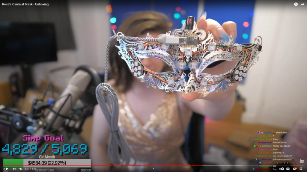
“This” is a Carnival Mask with 23 NeoPixel LEDs controlled by an ADAFruit QT PY micro-controller. It was made to be used as a wall- or shelf-decoration but can be worn with a little preparation.
“Rose” is the en femme persona of F1nn5ter, a popular YouTube Minecraft and Twitch streamer. Her birthday was established to be April 30th 2020 and the mask was made on the occasion of her “first birthday.” In reality, she inherits the actual age (21) of F1nn.
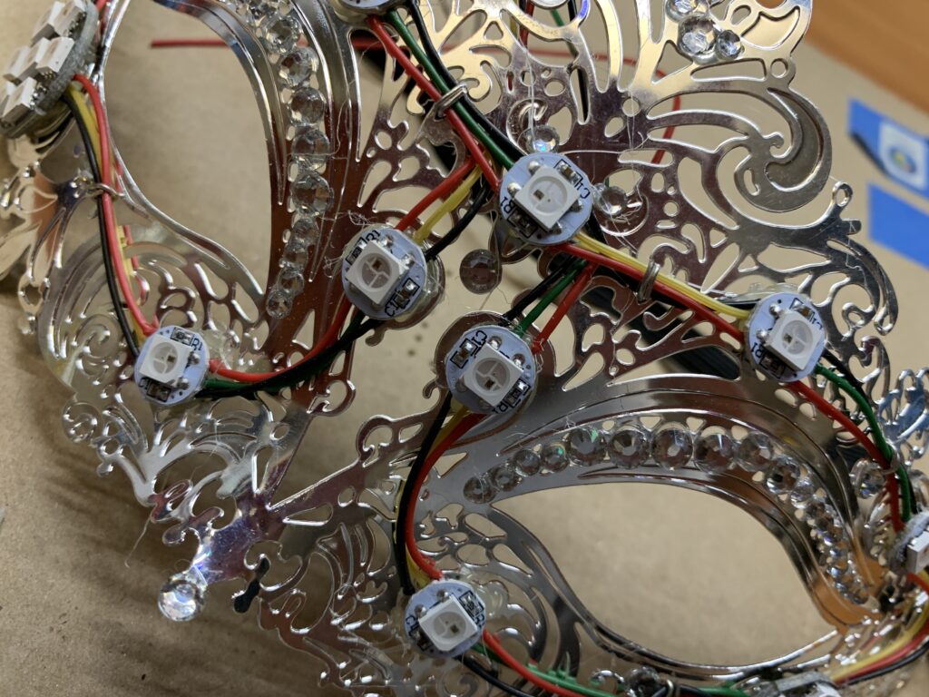
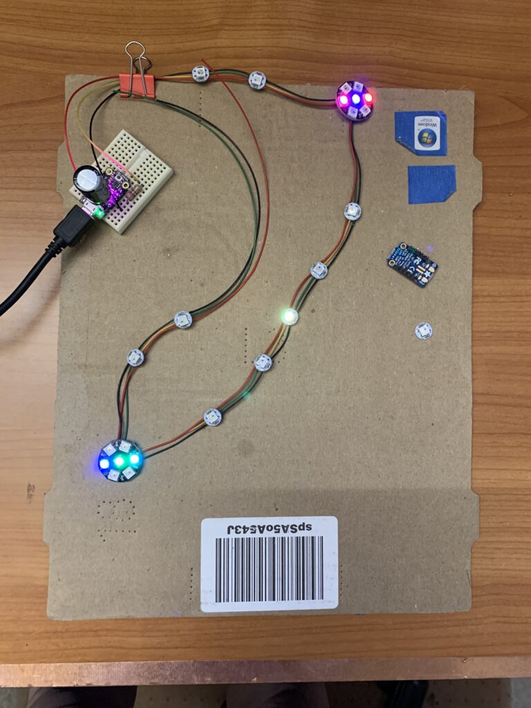
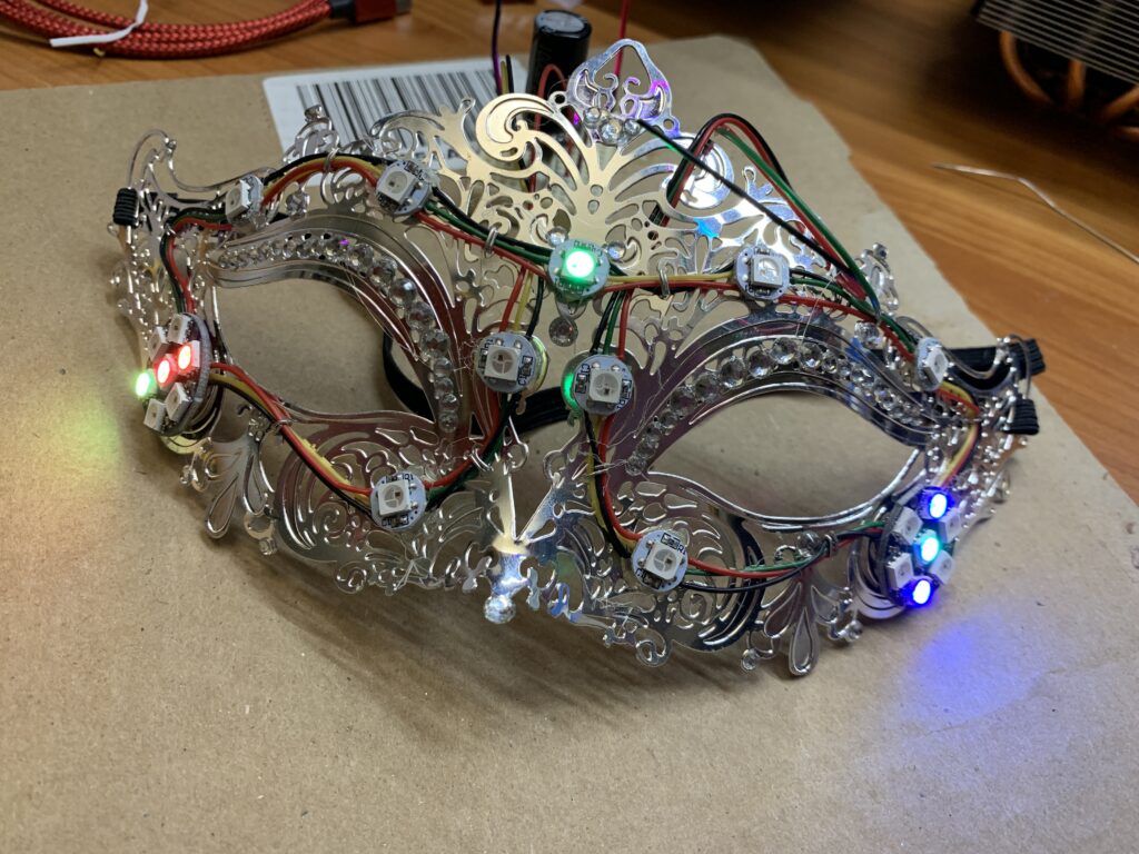
Build Process Photos: Assembling LED String
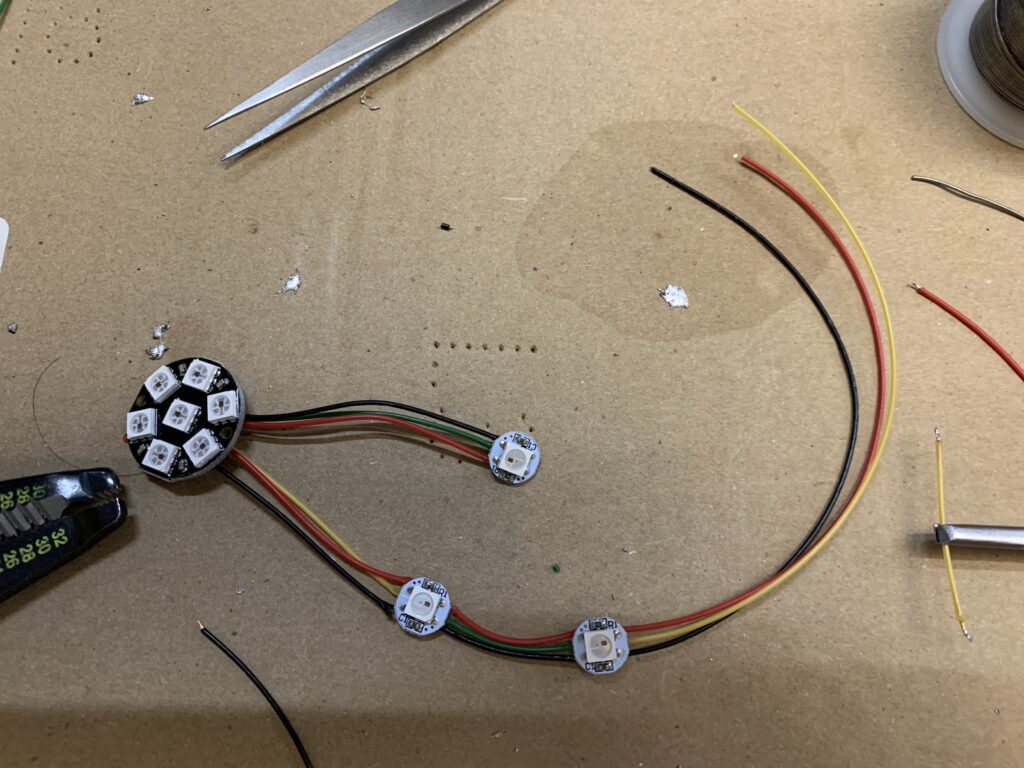
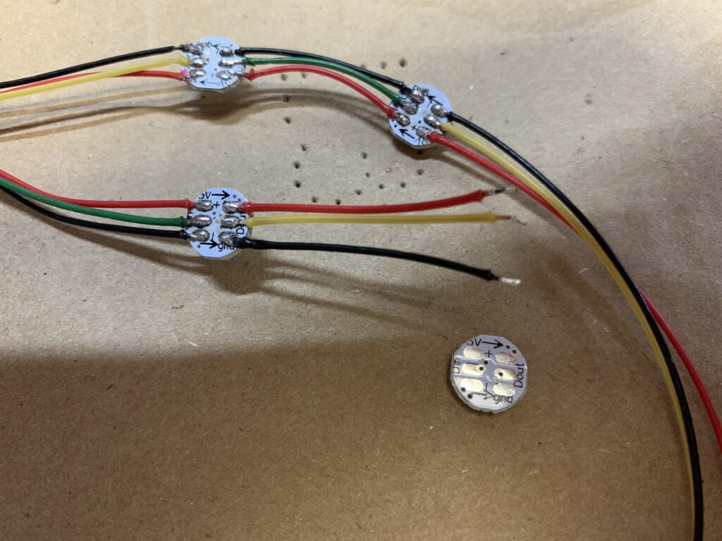
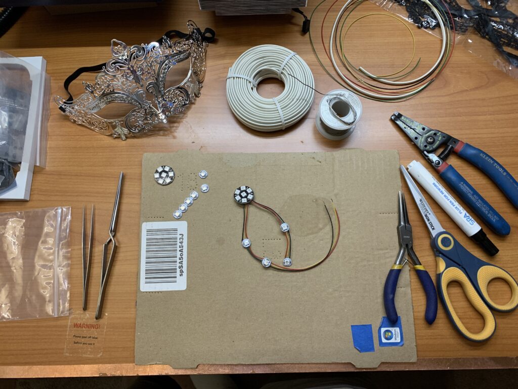
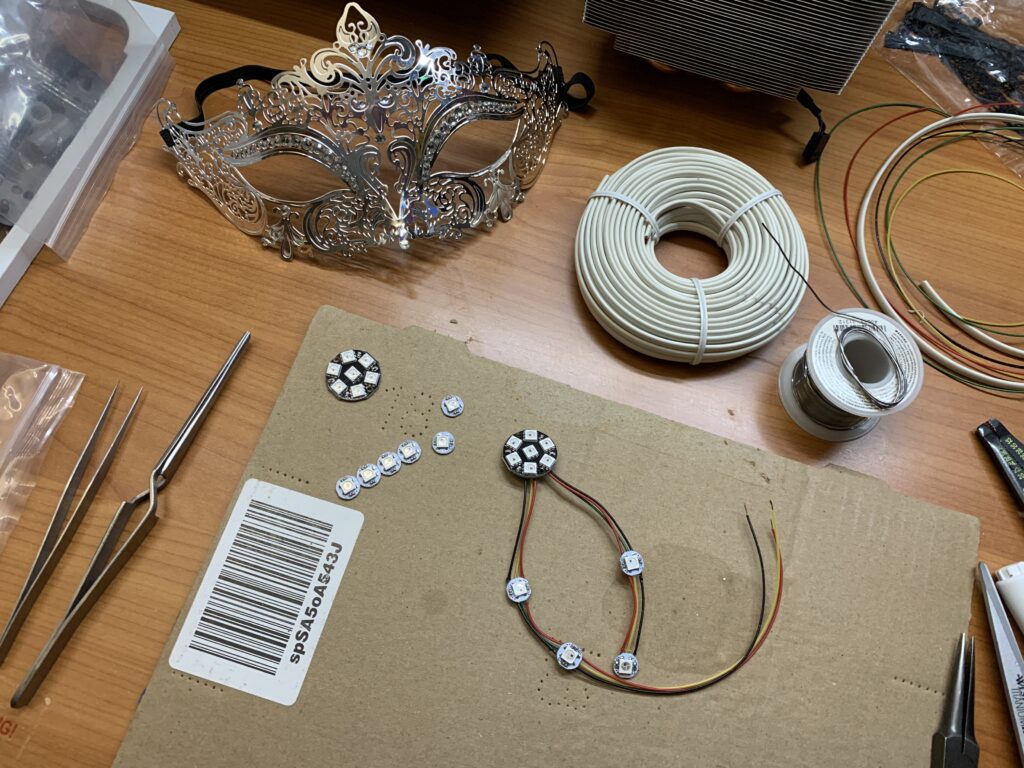
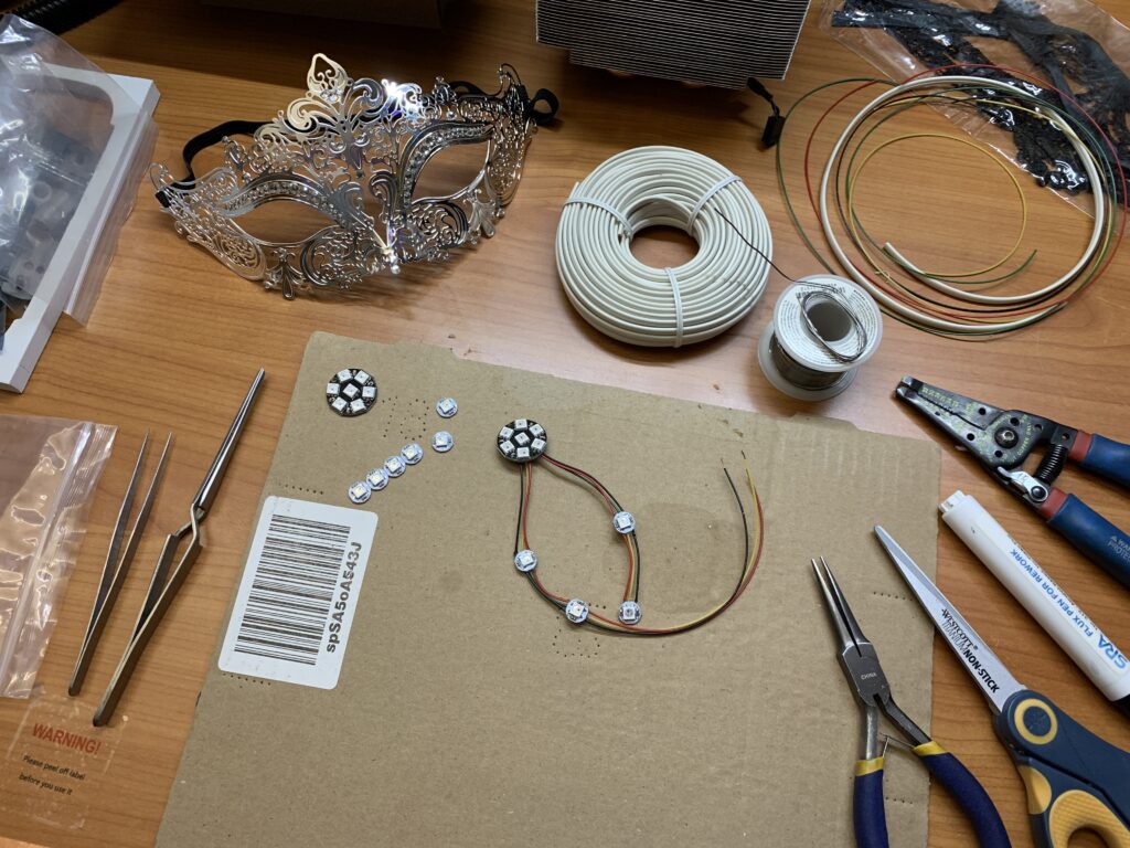
NeoPixel LEDs were used since they are addressable RGB LEDs that can be programmed to produce a a variety of colors with very little effort. Nine single NeoPixel modules and 2 7-NeroPixel discs were used.
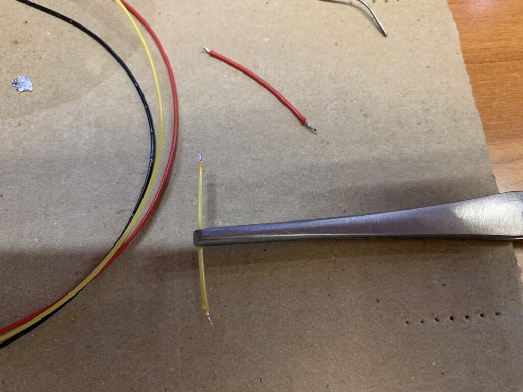
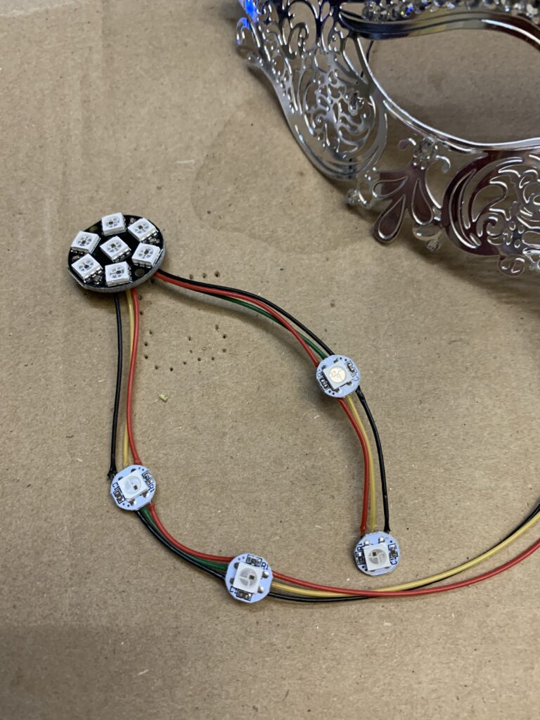
Stranded silver satin wire was used for the connections between the LED modules. After each LED was added to the string, the whole string was connected to a AdaFruit Trinket M0 to verify that the string was functional.
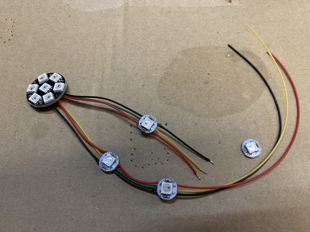
There were two sets of strings prepared—one for the right side of the Mask and one for the left side. The strings are mirror images of each other. Since each LED is addressed in the order they are wired, there is a distinct “first LED” which happens to be the one located immediately to the left of the right eye (left and right are from the perspective of the wearer). The second through eleventh LEDs are wired in order clock-wise from the first LED.
The twelfth LED is centered above the nose. The thirteenth through twenty-third LEDs run clockwise from the twelfth LED with the last LED ending up just opposite the first LED.
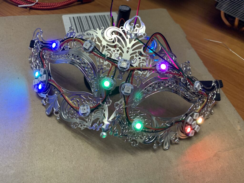
Build Process Photos: Mounting the LEDs and Basic Function Test
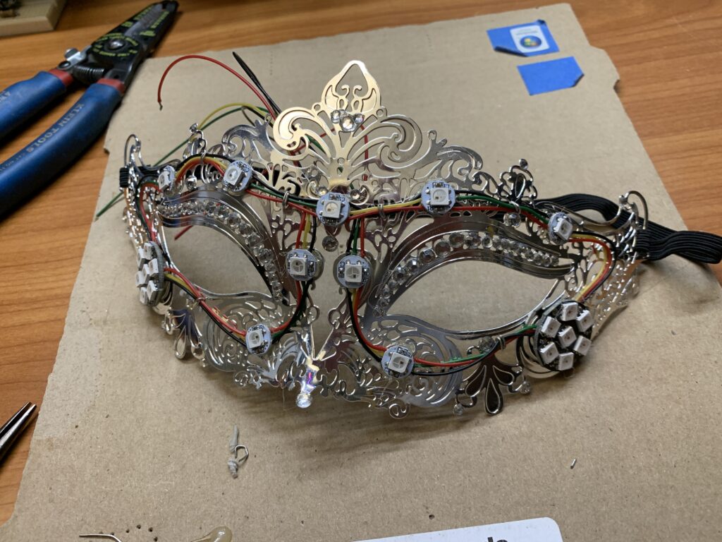
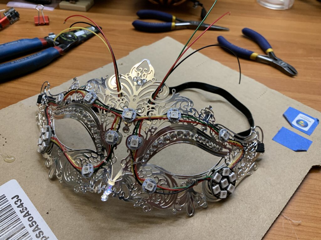
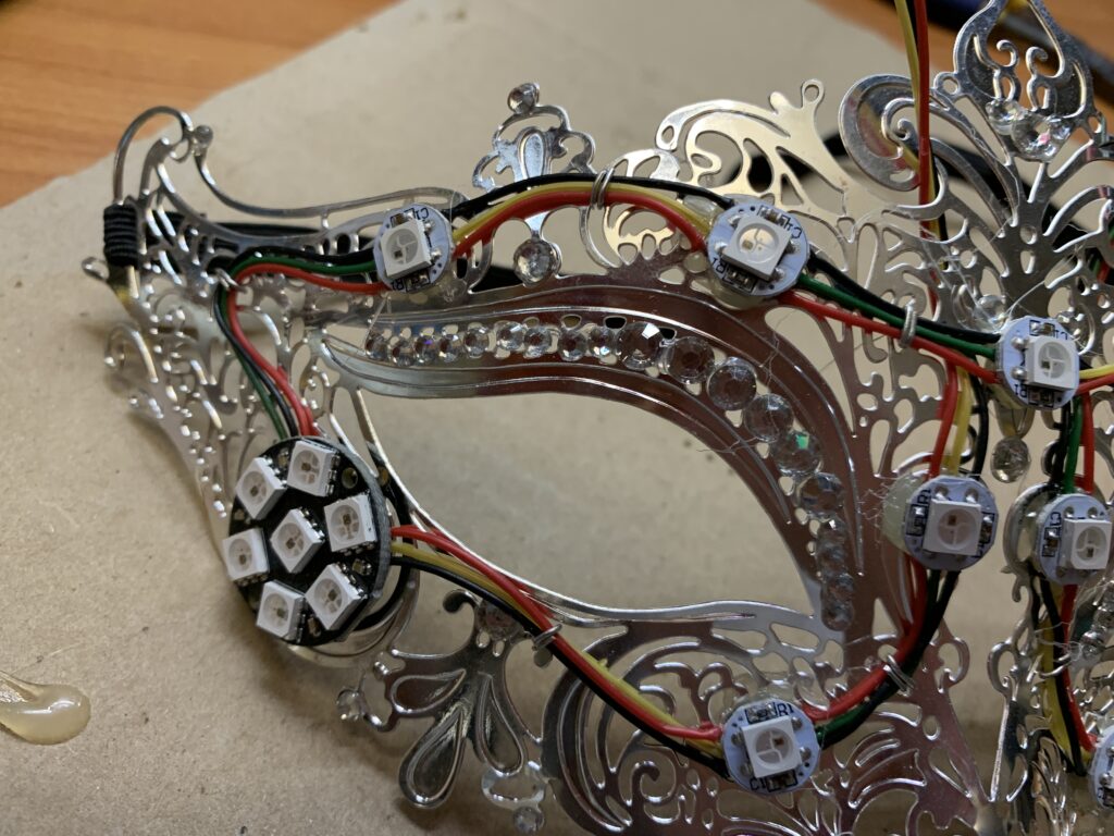
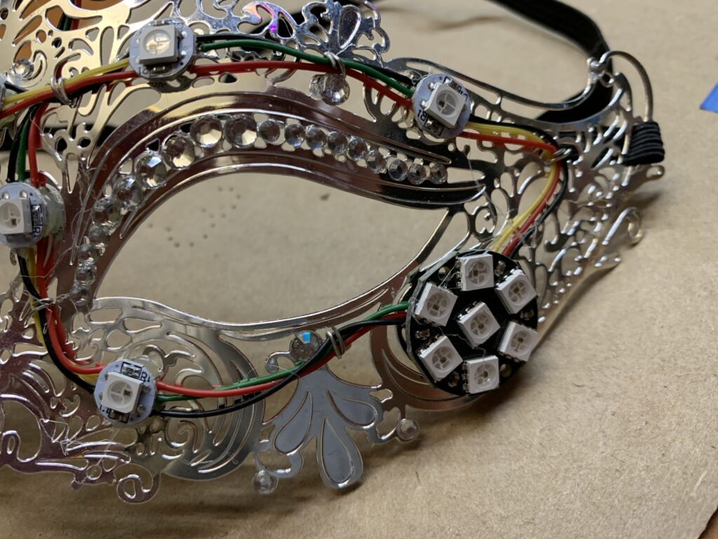
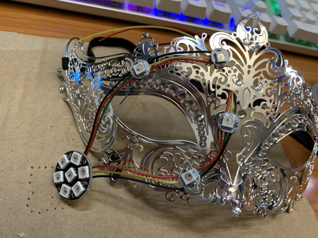
The finished strings of LEDs were mounted to the mask using hot melt glue. As each LED was pressed into its mounting location, molten glue would protrude through the perforations in the mask which improved attachment strength. Additional hot melt glue was applied from the back of the mask to reinforce the glue protruding through the mask.
Between each LED, the wiring was secured using a length of stripe, solid wire. This wire is intended to take up any strain the cable that might compromise the soldered connections.
The wires the the start and end of the string were routed through the mask perforations to meet in the middle of the mask above the nose where the micro-controller was to be mounted. At this stage of assembly, the Trinket M0 was still used to verify that the strings of LEDs were still working.
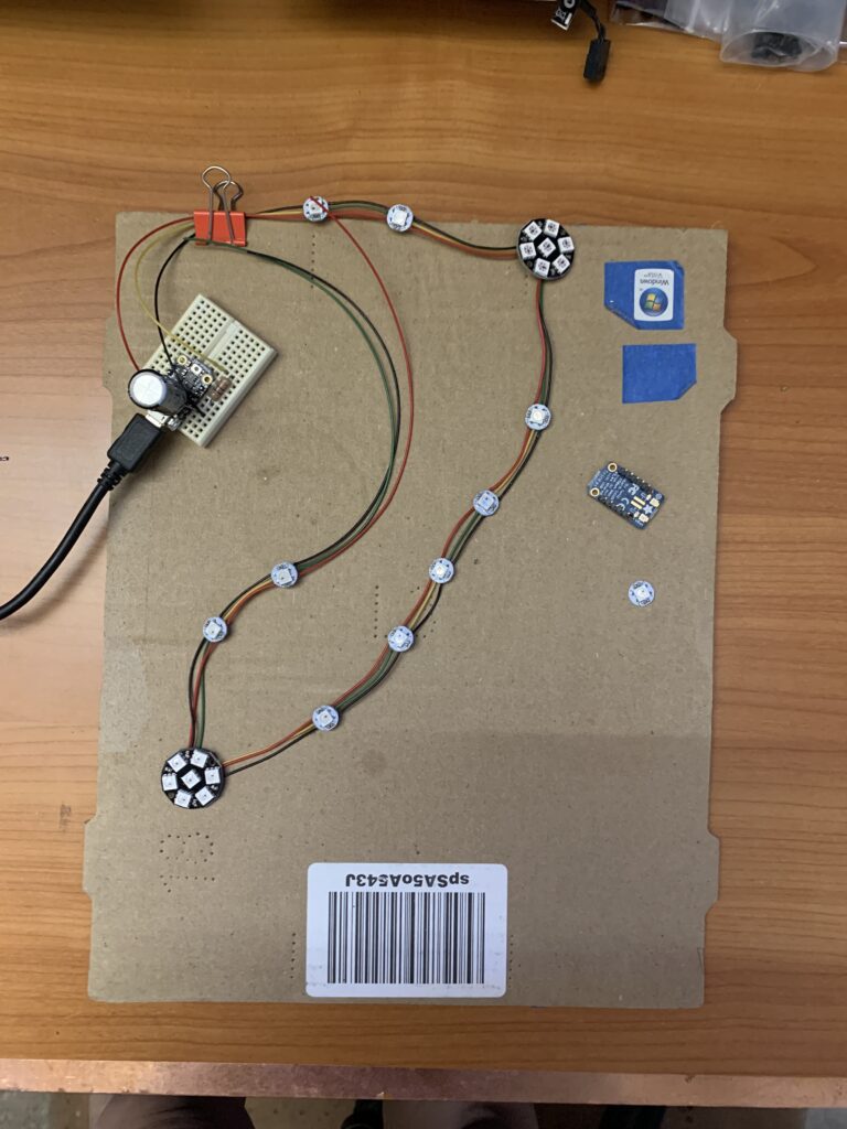
Build Process Photos: Initial Burn-In
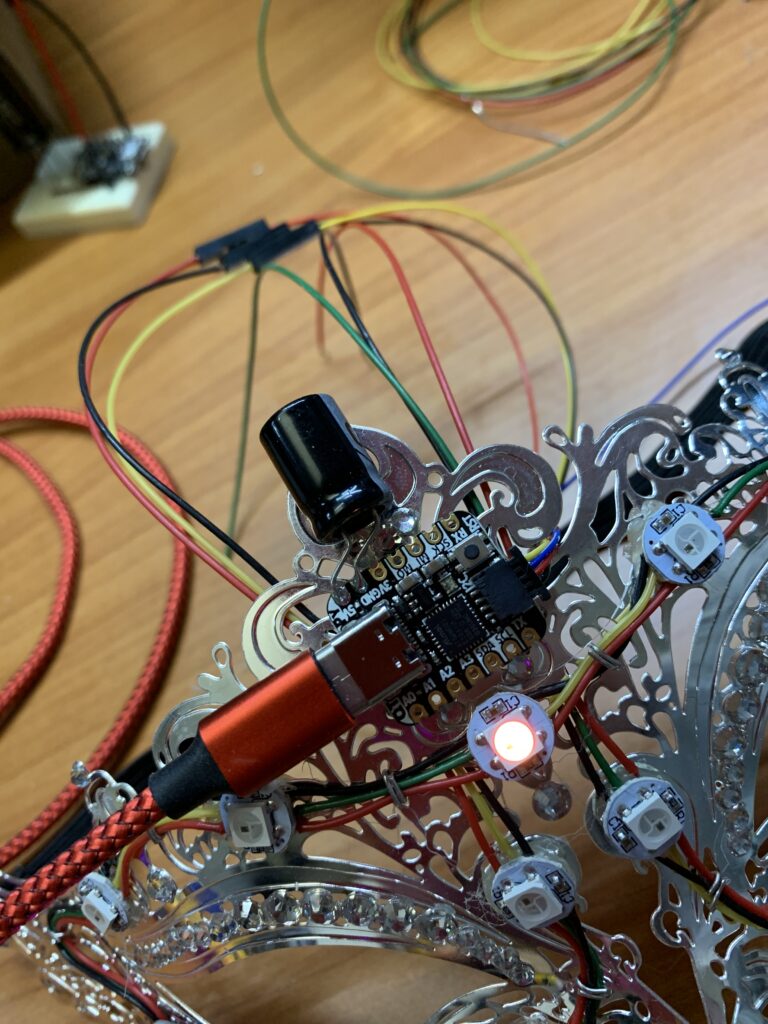
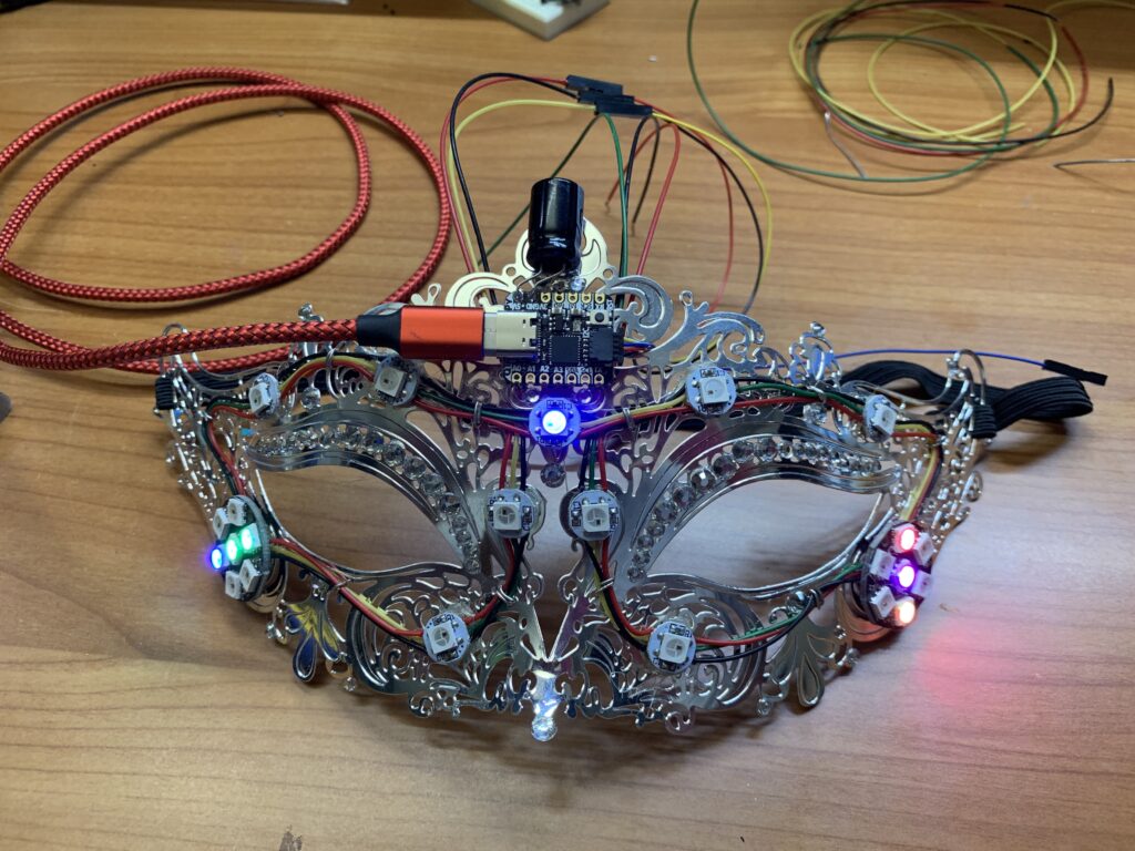
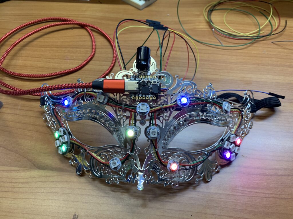
The AdaFruit QT Py micro-controller was mounted on the mask using 3M VHB double-sided tape. This tape was used for its bond strength and flexibility. For testing purposes, an available USB-C cable was used to power the system and a standard STEMMA QT harness was used to connect the STEMMA QT jack to the bare wires leading to the LEDs.
The Mask was operated in this manner for a few hours to verify that everything was working.
The QT Py micro-controller was programmed using the same code that was used on the Trinket M0 micro-controller. Both of these micro-controllers use the SAMD21 Cortex M0 chip and so they have equal processing power. The only difference between them is the form-factor of the circuit board and resulting connectivity.. The Trinket M0 has more available pins, is on a slightly larger PCB, and uses a Micro-USB port for power and programming.
The QT Py has a much smaller PCCB and uses a USB-C connecter for power and programming. It also has a a STEMMA QT connecter which is a 4-wire socket intended to carry 5V+, ground, and i2c signals. For this project, only one signal was needed (the serial data pin for the NeoPixel LEDs) so the second wire is present but unused.
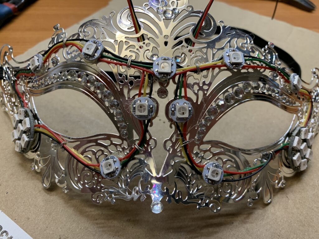
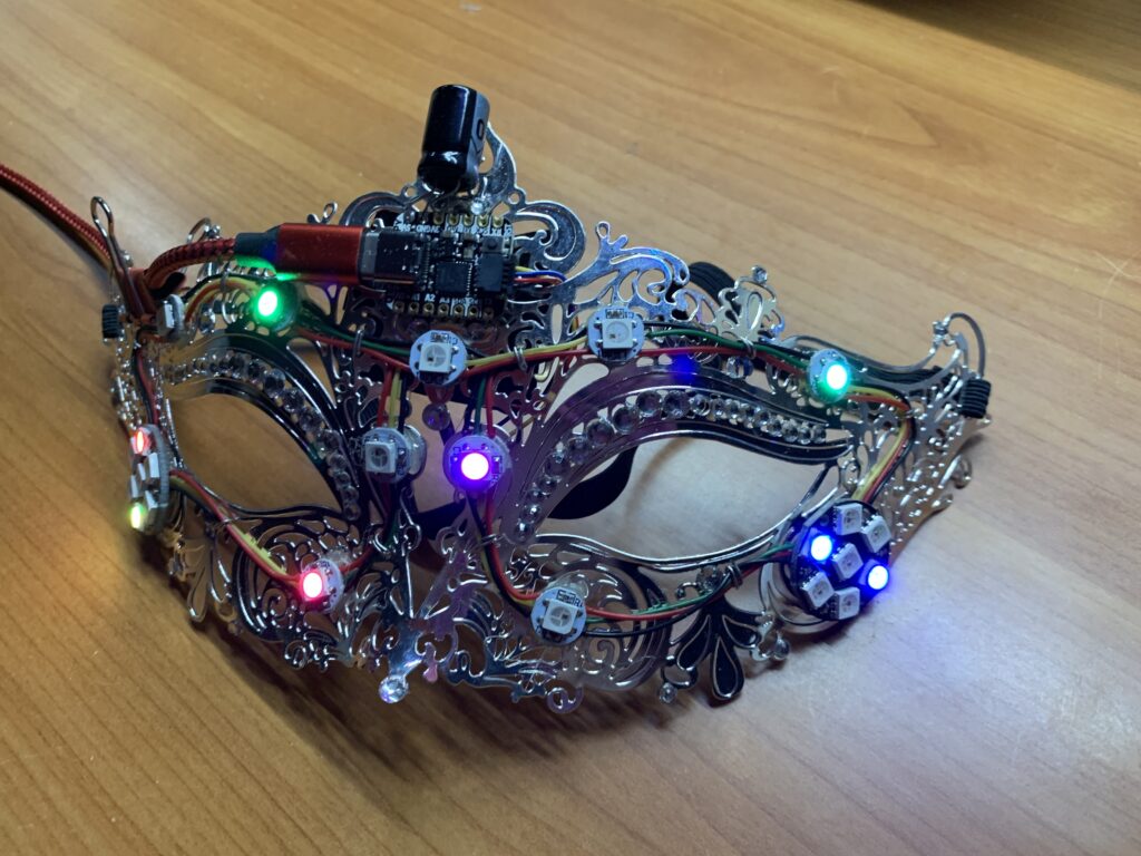
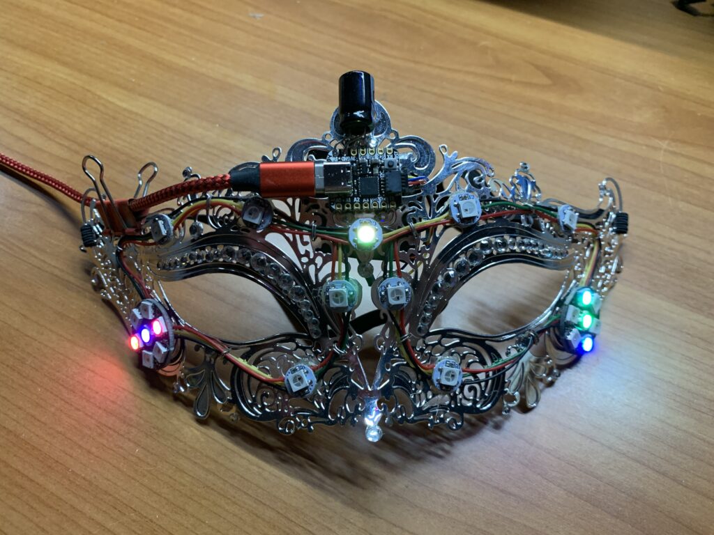
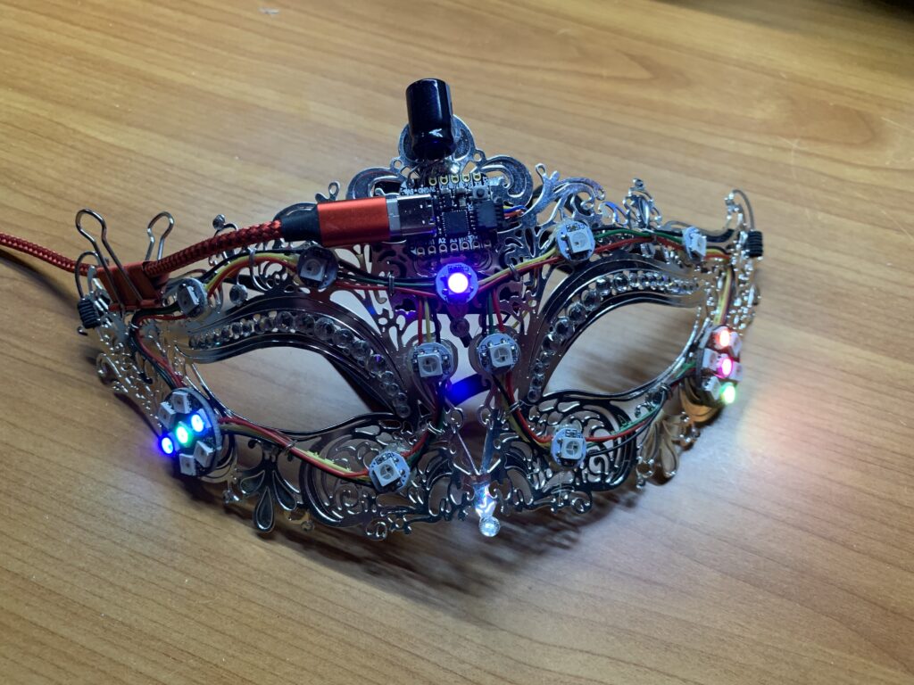
Build Process Photos: Final Burn-In
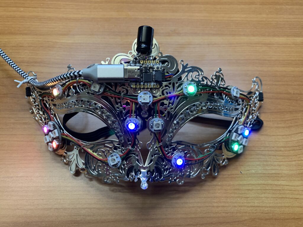
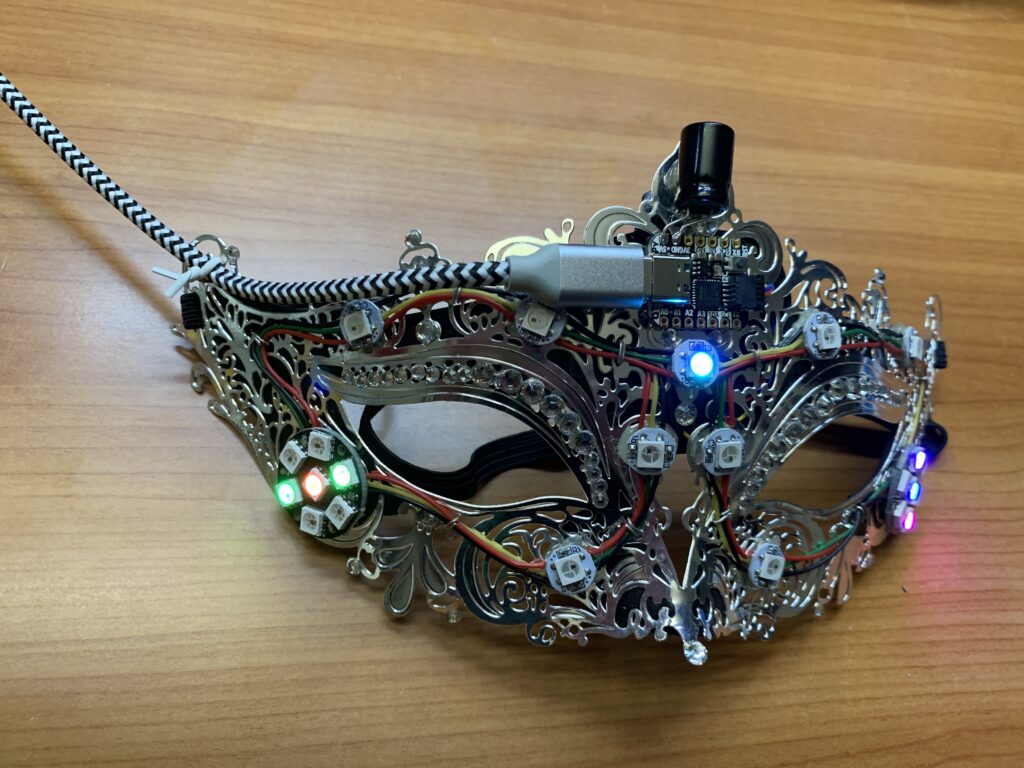
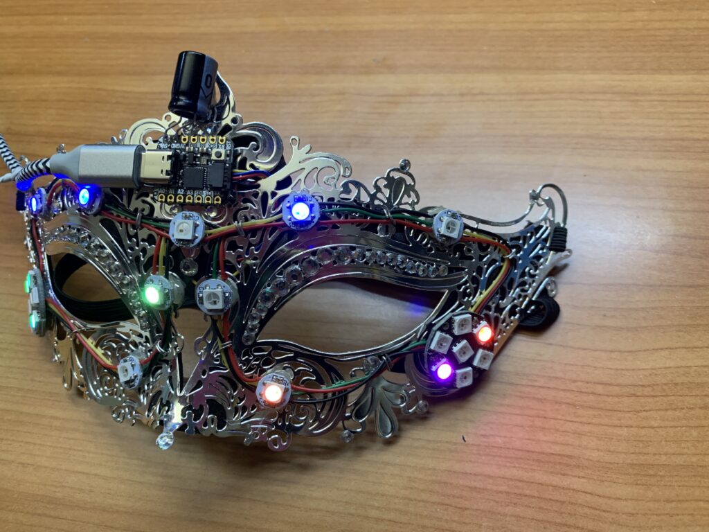
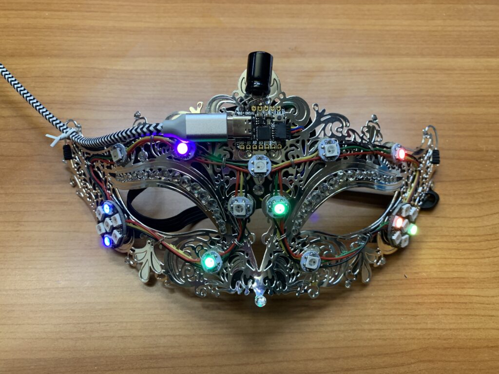
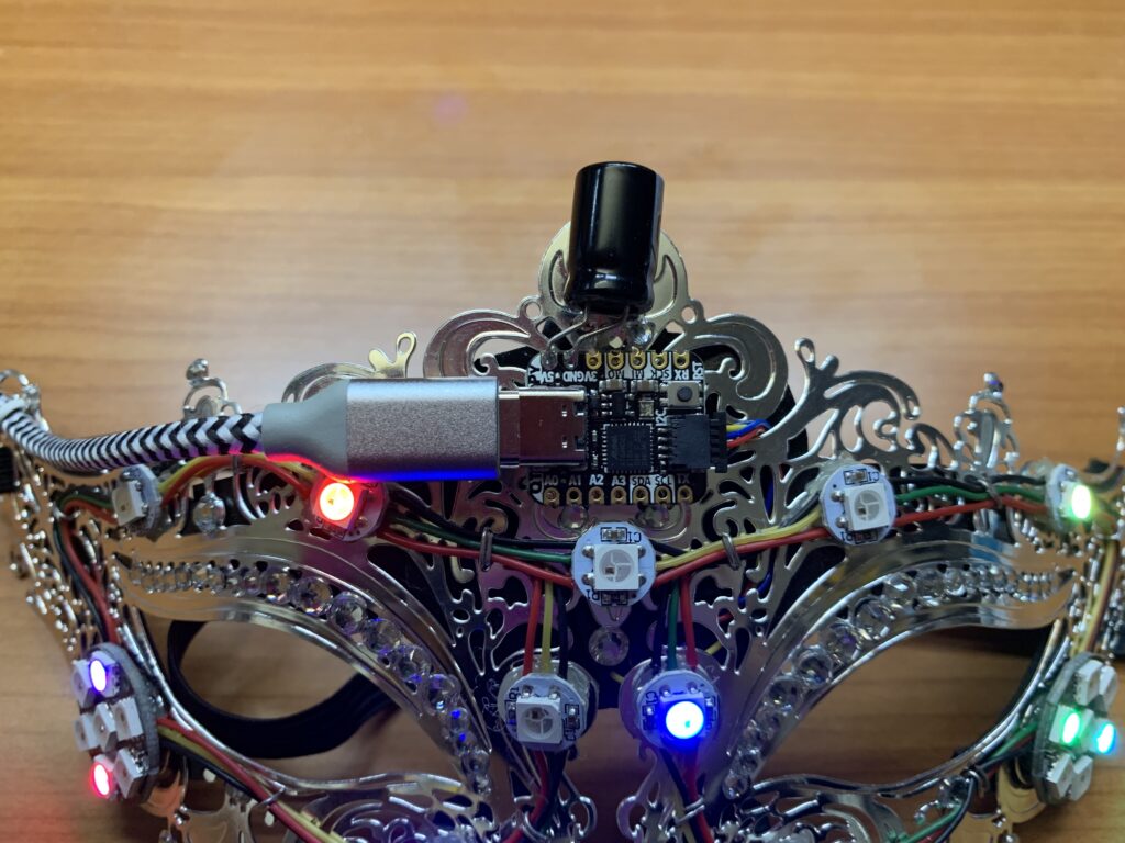
The Mask was set-up in its final, end-user configuration. The LEDs are connected to the QT Py via the STEMMA QT jack. The wires from the STEMMA QT jack carry 5V+, ground, and serial-data. 5V+, ground, and serial-data wires were spliced onto the wires leading to the first LED. The 5V+ and ground from the last LED were spliced in parallel with the corresponding wires of the first LED to compensate for voltage drops caused by the use of the thin wiring.
The Mask was operated for several hours using the QT Py micro-controller and the USB cable that was to be shipped to the end-user. This verified that the Mask was fully functional in and of itself.